
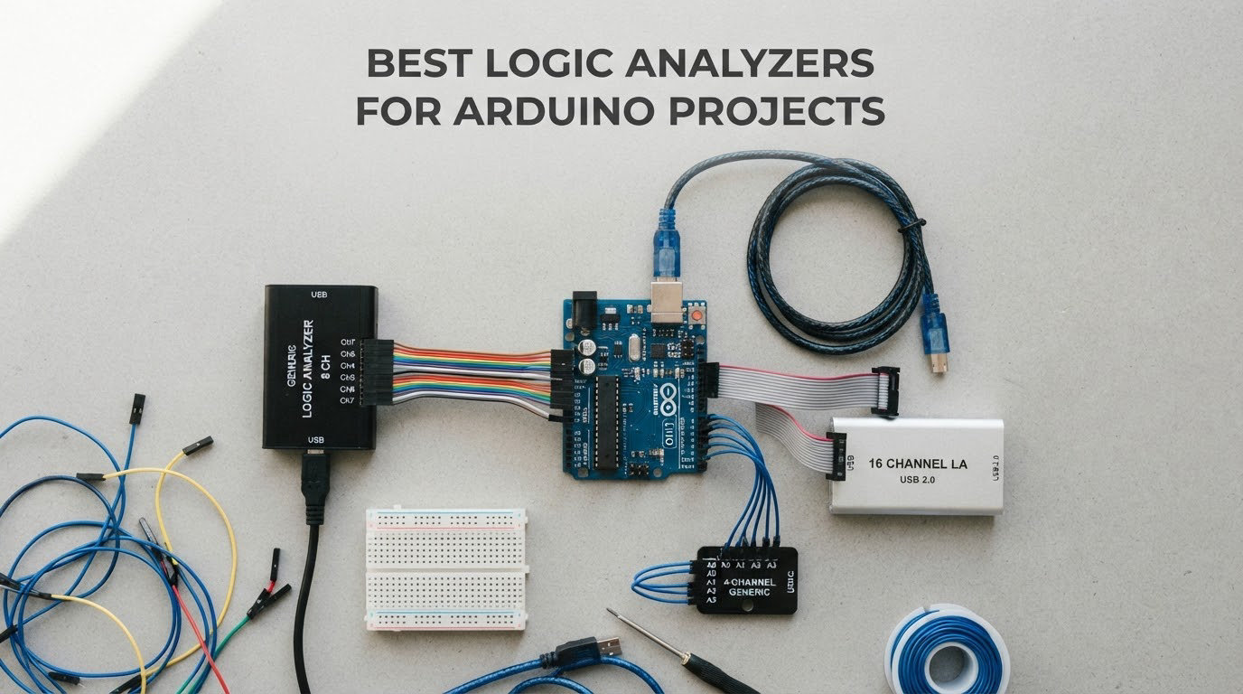
Serial buses carry no visible labels. When an Arduino Uno talks to a sensor over I2C and nothing happens, you cannot see a single bit of it from the serial monitor, and you are left guessing at addresses, baud rates and clock timing. A logic analyzer closes that gap: it clips onto a handful of wires, records the high and low state of every one of them at the same instant, and decodes the traffic into readable transactions.
After months of comparing these across breadboards, sensor boards and SPI flash chips, the honest conclusion is that the best logic analyzers for Arduino projects are not the most expensive ones. Most of the work a hobbyist does happens on slow buses where a 24MHz eight-channel analyzer captures every transition with room to spare. Free sigrok and PulseView software handles the decoding, and the total cost of getting a useful capture on screen is a rounding error compared with the rest of a parts bin.
What follows is a tier-by-tier roundup of ten devices, from the entry-level 24MHz units that most people should start with up to the professional hardware that few Arduino makers ever need. I have leaned on the forum consensus, which has barely shifted in a decade, that a modest analyzer plus good open-source software is genuinely enough for the overwhelming majority of embedded work. We also cover the sample-rate math that tells you when that stops being true, the ground-clip technique that decides whether a capture is readable or garbage, and where a plain multimeter or an oscilloscope is the better tool. Pricing in this category moves fast, so every product here links to a live listing rather than quoting a figure that will be stale by next month.
Table of Contents
Top 3 Picks for the Best Logic Analyzers for Arduino Projects (October 2026)
If you want the short version, these are the three that earn a place on a working bench. The HiLetgo is the default first purchase, the innomaker LA1010 is the step-up, and the Comidox is the bare-bones option when you already own test leads.

HiLetgo 24MHz 8-Channel Analyzer
- 24MHz sampling on 8 channels
- Enumerates as a Saleae device
- Input range -0.5V to 5.25V

Innomaker LA1010 16-Channel 100MHz
- 16 channels at 100MHz
- 30 plus protocol decoders
- Color-coded connectors
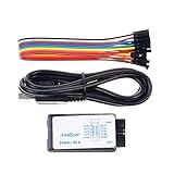
Comidox 24MHz 8-Channel Analyzer
- 8 channels
- 24MHz maximum
- Works with Saleae and PulseView
- Includes 10 Dupont lines
All 10 Logic Analyzers Compared in 2026
The table below is the whole roundup on one page. Every device here decodes I2C, SPI and UART in some form, so the columns that actually separate them are channel count, sample rate, buffer behavior and whether analog inputs are included.
| Product | Specifications | Action |
|---|---|---|
| HiLetgo 24MHz 8-Channel USB Logic Analyzer |
|
Check Latest Price |
| Innomaker LA1010 16-Channel 100MHz Logic Analyzer |
|
Check Latest Price |
 Digilent Digital Discovery Digilent Digital Discovery |
|
Check Latest Price |
| Comidox 24MHz 8-Channel Analyzer |
|
Check Latest Price |
 Saleae Logic 8 Saleae Logic 8 |
|
Check Latest Price |
 LONELY BINARY 8-Channel Analyzer Kit LONELY BINARY 8-Channel Analyzer Kit |
|
Check Latest Price |
| Saleae Logic Pro 8 |
|
Check Latest Price |
 DSLogic Plus 16-Channel 400MHz DSLogic Plus 16-Channel 400MHz |
|
Check Latest Price |
 EspoTek Labrador Multi-Tool EspoTek Labrador Multi-Tool |
|
Check Latest Price |
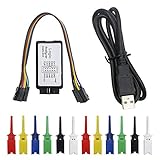 KeeYees 24MHz 8-Channel with Test Hooks KeeYees 24MHz 8-Channel with Test Hooks |
|
Check Latest Price |
1. HiLetgo 24MHz 8-Channel USB Logic Analyzer – Best First Buy
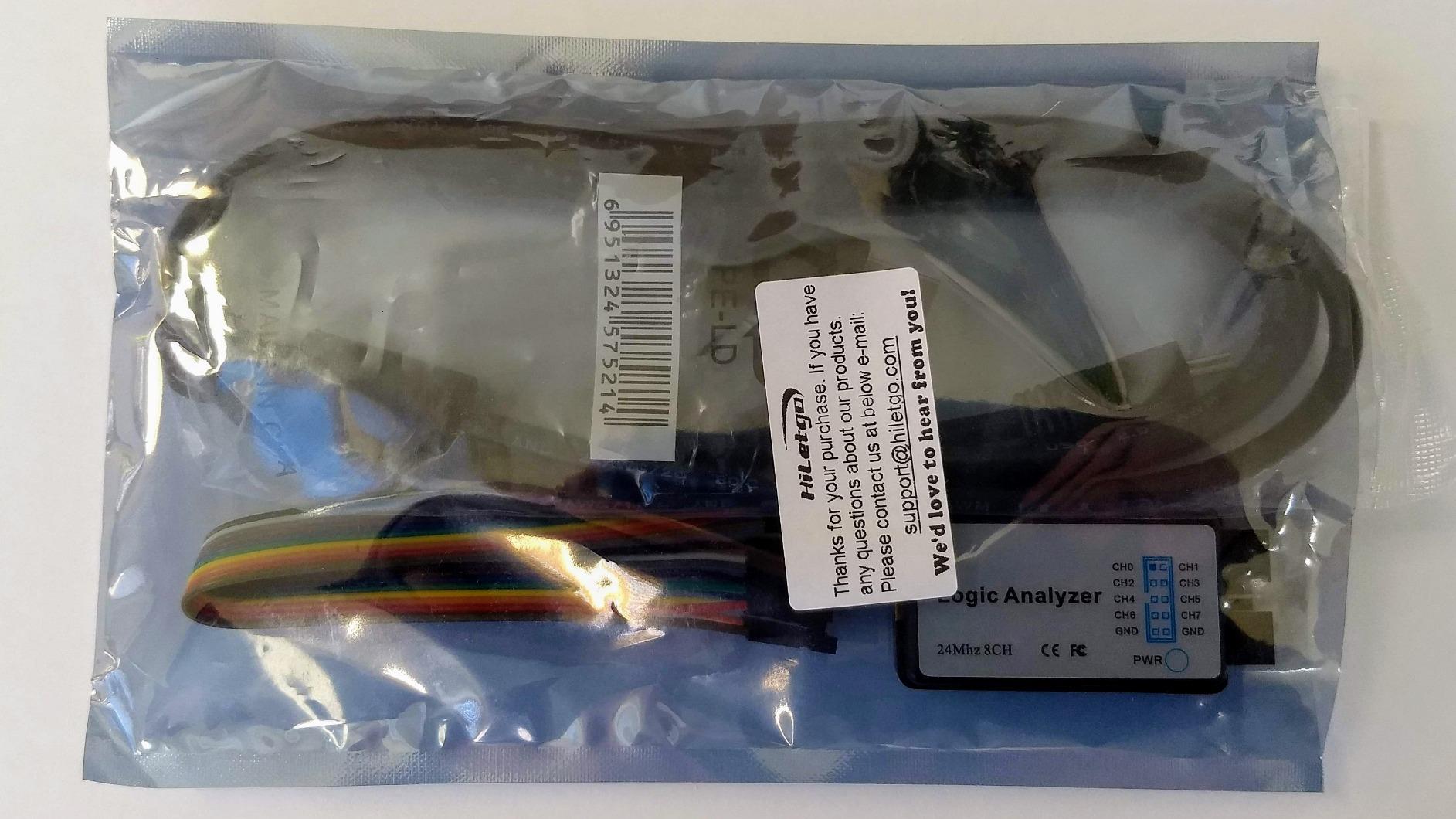
HiLetgo USB Logic Analyzer Device with EMI Ferrite Ring USB Cable 24MHz 8CH 24MHz 8 Channel UART IIC SPI Debug
24MHz per channel
8 channels
-0.5V to 5.25V input
1Mohm
10pF impedance
Pros
- Enumerates as a Saleae device so both open-source and commercial software work
- 589 reviews give the widest owner feedback in this roundup
- Enough channels to cover SPI MISO MOSI CLK and CS
- USB powered with no external supply
Cons
- No on-board capture buffer so heavy USB traffic can distort or drop data
- Inputs protected only by series resistors
- Some laptop USB ports refuse the driver
This is the unit that ends up on more benches than anything else in the category, and the reason is simple: it is the cheapest device that identifies itself as a Saleae Logic analyzer over USB. That single detail is what makes it plug into the free sigrok and PulseView stack without any driver gymnastics, and it also means the commercial Saleae software will talk to it if you ever want a friendlier interface.
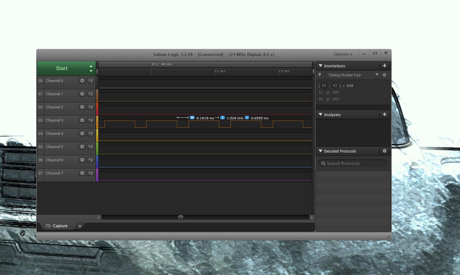
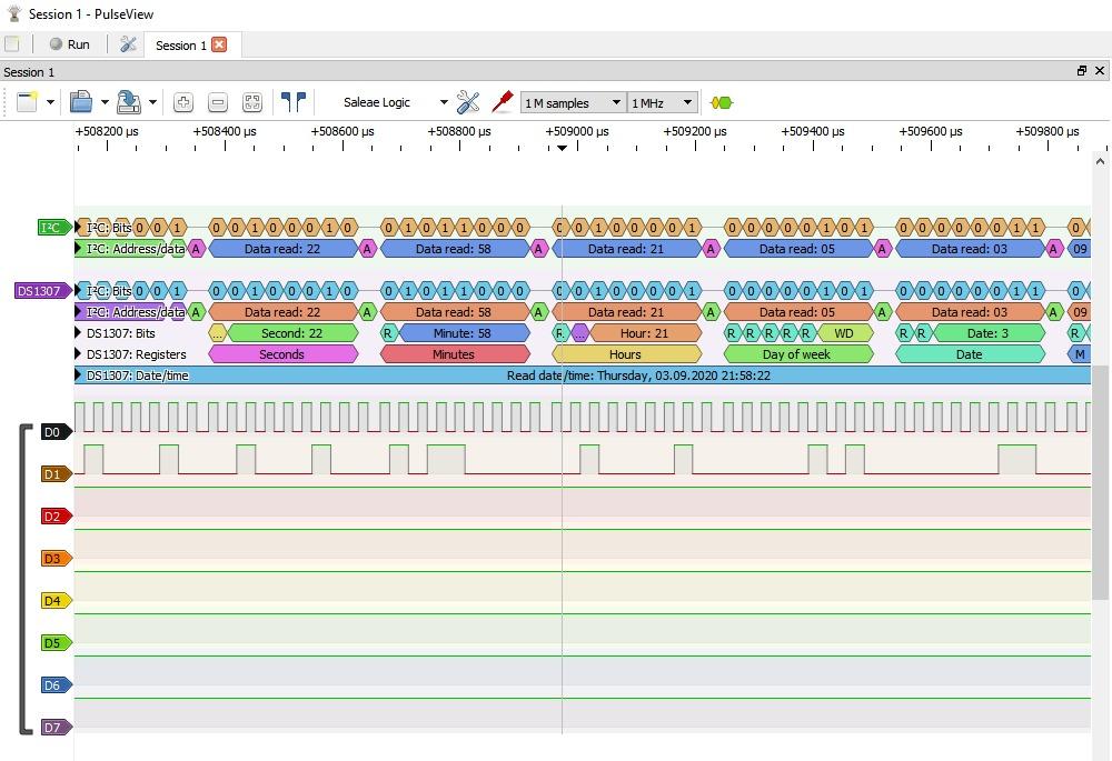
For Arduino work, eight channels at 24MHz is a comfortable match. An SPI transaction needs four wires, I2C needs two, and the extra four give you room to catch a chip-select, an interrupt line or a reset pulse while the bus is running. Sampling is selectable from 24MHz all the way down to 25KHz, which matters because dropping the rate is the simplest way to clean up a noisy capture on a breadboard.
The build is honest about what it is. Input range runs from -0.5V to 5.25V with roughly 1Mohm parallel 10pF impedance, and the logic threshold treats anything above 2.0V as a high. That threshold is a real quirk on a 5V circuit, because 2.0V sits close to where a slow-rising signal is still settling, so noisy breadboards can produce phantom transitions. Dropping the sample rate is the fix most people find first.
Two honest complaints come up repeatedly in the 589 reviews of this unit. The first is that there is no on-board buffer, so all the sample data has to move over USB fast enough to keep up, and a busy bus on a slow port can produce distorted or incomplete traces. The second is documentation: nothing is included in the box, and on Windows you typically need Zadig to swap the stock driver for WinUSB before PulseView will see it. A few owners also report that particular laptop USB ports reject that driver entirely, which a powered hub resolves.
What 8 channels at 24MHz actually resolves for you
Twenty-four megahertz gives you about 41 nanoseconds between samples, which is roughly a hundred times finer than the 4 microseconds a single bit takes on a 100KHz I2C bus. In practice that means you can see the individual clock edges, the setup and hold margins, and the gap between transactions. It also means a 16MHz SPI bus has only 1.5 samples per clock cycle, which is enough to see the shape of a transfer but not enough to trust the bit timing on a marginal signal.
For I2C, SPI at 4MHz and 8MHz, UART and one-wire, 24MHz is not a compromise. It is more resolution than the signal needs, and additional bandwidth buys you nothing but longer files.
When a different analyzer is the smarter buy
Move up if you need to watch a full data bus rather than the control lines, if your SPI runs at 16MHz or faster, or if you want to look at analog behavior on the same pins. Anyone probing surface-mount IC pins rather than header pins will also want a kit that includes proper test hooks. For everything from sensor bring-up to I2C address scanning to reading a startup sequence, this is the right first purchase.
2. innomaker LA1010 16-Channel 100MHz Logic Analyzer – Best Value Upgrade
innomaker LA1010 USB Logic Analyzer 16 Input Channels 100MHz with the English PC Software Handheld Instrument,Support Windows (32bit/64bit),Mac OS,Linux
16 channels
100MHz per channel
30 plus protocol decoders
KingstVIS software
Pros
- 100MHz gives real headroom above the 24MHz clones
- 16 channels lets you watch a full byte bus in one capture
- Color-coded connectors match on-screen waveform colors
- English software and manual
- Works on Windows macOS and Linux
Cons
- Display refreshes roughly once a second so it is not a smooth real-time view
- Probe grabbers are unnumbered and colors do not always match
- Some listings ship an older USB-B port and a software CD
The LA1010 is the step-up that makes sense the day you run out of channels rather than bandwidth. Sixteen inputs at 100MHz per channel is a genuine jump: at 100 megahertz you get 10 nanosecond resolution, and the device is no longer the limiting factor on anything an Arduino Uno talks to.
Its software, KingstVIS, is the reason many buyers stay. The decoder library runs past 30 protocols, covering UART and RS-232 and RS-485, I2C, SPI, CAN, DMX512, HDMI CEC, I2S, JTAG, LIN, Modbus, one-wire, SDIO, SMBus, PS/2, NEC infrared and parallel buses. Several of those, particularly CAN and Modbus, are impossible on a bare clone without adding hardware, so the library alone justifies the move up for anyone touching a vehicle bus or an industrial sensor.
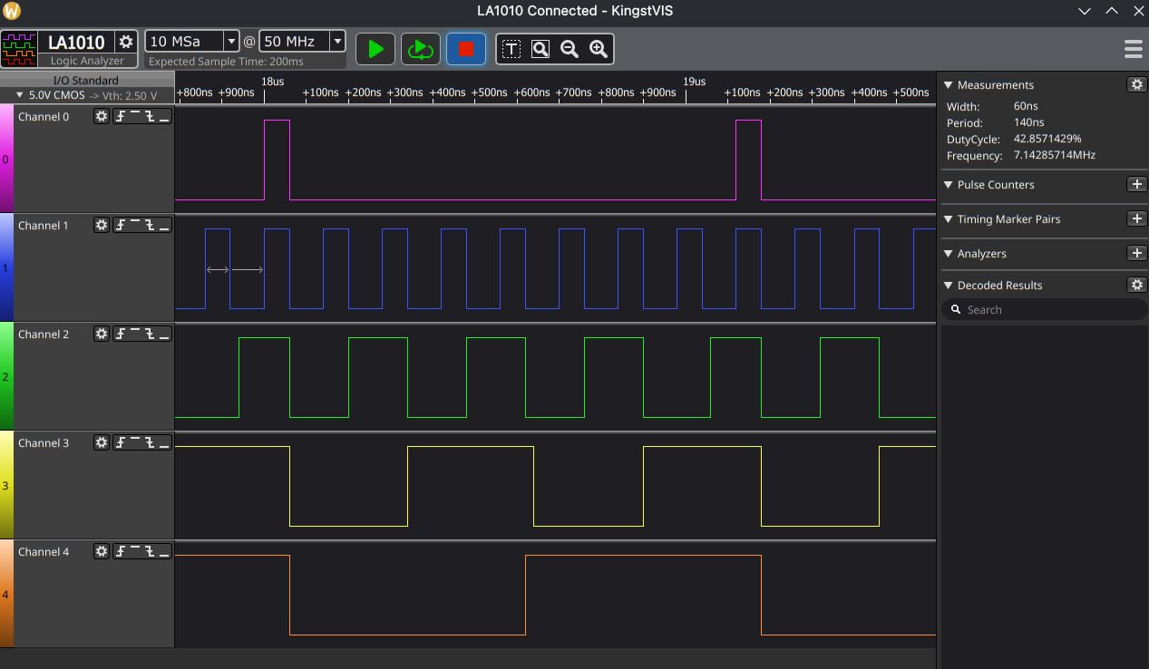
The English translation of the interface and the printed manual are quietly important, and they are the first thing reviewers mention. A device that is technically capable but documented in a language you do not read is a frustrating tool, and this one avoids that problem. Captures save with a time-range export dialog, so you can pull out the one millisecond you care about instead of shipping a huge file to a colleague.
The two complaints that recur are display behavior and probe labeling. The screen refreshes in intervals of roughly a second, so it does not feel like a live scope, though it is perfectly usable for trigger-then-inspect work. More irritating is that the probe grabbers are unnumbered and their colors do not always match the wires they came with, so tracking more than six or seven signals in a wide capture becomes genuinely difficult. Color-coded connectors on the unit help; the loose leads do not.
Whether 16 channels changes how you work
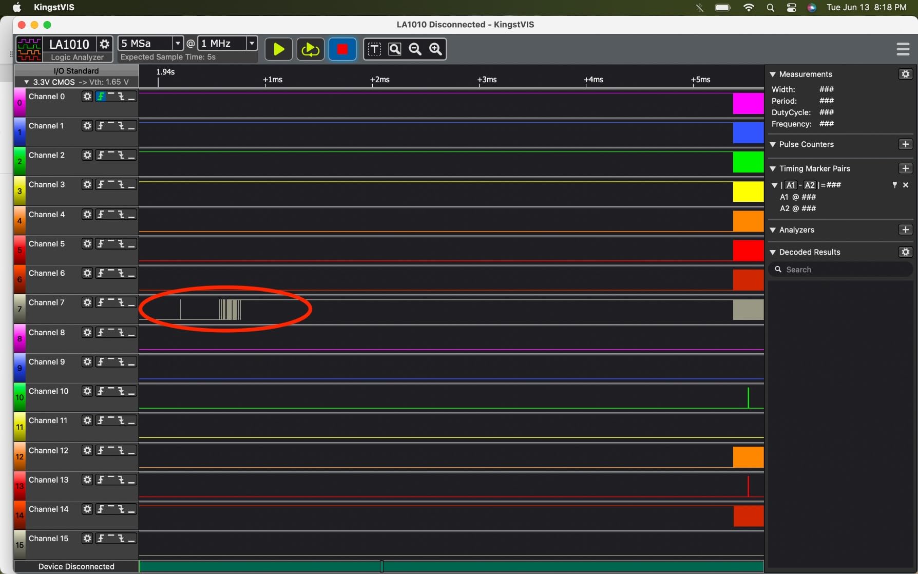
Eight channels is enough to see the conversation. Sixteen is enough to see the whole conversation at once, which matters for anything with a parallel bus, a multi-bit data line, or a bus plus its associated control and interrupt lines. If your projects involve a display, a memory chip or an encoder with index and quadrature outputs, the extra channels remove the guesswork.
Pair the bandwidth jump with the decoder library and this becomes the most capable analyzer in the roundup for mainstream embedded work. It is the choice for a maker who has already outgrown a clone and does not want to jump straight to professional pricing.
Where the trade-offs bite
The single-second refresh means this is a capture-and-inspect instrument, not a scope substitute, and anyone expecting a rolling realtime display will be disappointed. If your workflow is watching a signal as you change a potentiometer, add a cheap scope to the bench rather than waiting on this. Watch for listings that ship the older USB-B connector and a CD instead of a current cable, and be aware that a small number of owners report units that never registered a voltage reading at all.
3. Digilent Digital Discovery – Best With a Pattern Generator
Digital Discovery: Portable USB Logic Analyzer and Digital Pattern Generator
32 channels at 800MS/s
16-channel pattern generator at 100MS/s
Protocol analyzer and power supply
WaveForms software
Pros
- Analyzer and pattern generator in one portable unit
- 32 channels gives room for wide buses and lots of control lines
- Free WaveForms software for Windows Mac and Linux
- Also supplies regulated power and static I/O
Cons
- Only 19 ratings so owner feedback is thin
- Flywire-only connections need care on a dense breadboard
- Costs well above the entry tier without matching Saleae software polish
The Digital Discovery is the odd one out in this roundup because it does something none of the other devices can: it generates signals. A 16-channel pattern generator running at up to 100MS/s means you can drive a bus from the tool itself, which turns a passive debugging accessory into a bench instrument that can test a slave device without writing a sketch.
The analyzer half is enormous by hobbyist standards. Thirty-two channels at up to 800MS/s puts it in a different league from everything else on this list, and combined with the onboard power supply, the static I/O source and the protocol analyzer mode, it covers most of what a low-speed bench needs in a single 3 by 6 by 8 inch box weighing 6.4 ounces. WaveForms, the software, is free and runs on all three major platforms.
When a pattern generator changes your workflow
Pattern generation matters more than most hobby guides admit. Verifying that your I2C sensor actually responds to a known address requires driving that address yourself, and doing it from a sketch means a rebuild, a reflash and a reset cycle every time. Here you can hold a capture-triggered pattern, clock a bus while the analyzer watches the response, and iterate in seconds. For anyone reverse-engineering a device that only speaks when spoken to, that is a real capability rather than a gimmick.
It is also the natural tool for FPGA work, where parallel buses at moderate speeds are the norm and 32 channels removes the need to capture in pieces.
Why the owner feedback is thin
Only 19 ratings exist for this device, and 4.1 out of 5 is the lowest average in this roundup, with roughly 54% of ratings at five stars and 23% at four. The rating distribution is favorable, but a sample that thin tells you very little. Treat the specifications as trustworthy because they come from the manufacturer, and treat peer opinion as essentially absent.
Two practical warnings for a hobbyist. The connections are flywires, which on a dense breadboard need deliberate routing to avoid crossing over the signals you are measuring. And the price sits far above the entry tier, which is defensible for FPGA or protocol work but hard to justify for debugging a sensor on an Arduino Uno. If pattern generation is not part of your project, this is not the device to buy.
4. Comidox 24MHz 8-Channel Analyzer – Best Bare-Bones Budget Pick
Comidox USB Logic Analyzer 24MHz 8 Channel Debug Tool for Arduino ARM FPGA
8 channels
24MHz maximum
0V to 5.5V input
1.5V logic threshold
Pros
- Drops straight into both Saleae software and free sigrok PulseView
- Sample rate selectable from 25KHz to 24MHz
- Automatic UART I2C and SPI decoding
- Ships with a USB cable and 10 Dupont lines
Cons
- 24MHz is low for modern high-speed serial links
- Fixed 1.5V threshold is unforgiving on non-TTL levels
- Bundled Dupont lines are basic compared with proper test hooks
Functionally, this is the same class of device as the HiLetgo, and the honest question is why you would pick one over the other. The answer is accessories. The Comidox ships with a USB cable and 10 Dupont lines in the box, so if you already own a drawer of test leads you can be capturing within minutes of opening the packet.
It is also listed as compatible with Saleae Logic software as well as supported by PulseView, which gives you the same dual-software flexibility as the higher-profile clone. Sampling runs from 25KHz up through 16MHz, 12MHz, 8MHz, 4MHz, 2MHz, 1MHz, 500KHz, 250KHz, 200KHz, 100KHz, 50KHz and finally 24MHz, and the lower rates are genuinely useful for making a noisy breadboard capture readable.
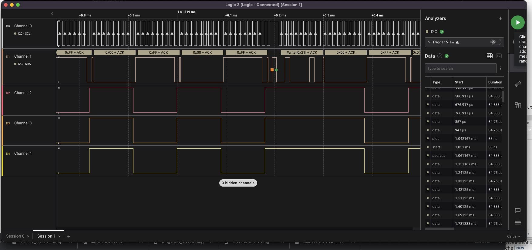
Automatic decoding of UART, I2C and SPI is built in rather than being a software plugin, which means first-time users see labeled transactions without configuring anything. The 155 reviews rate it 4.4 overall, and the feedback is consistent: capable budget analyzer, correct channel count, decodes the three protocols an Arduino maker cares about, ceiling is bandwidth.
The two limits are the same two that every 24MHz device has. The sample rate is low for modern high-speed serial links, and the fixed 1.5V logic threshold is less forgiving than a device with an adjustable threshold, particularly on 1.8V and 3.3V systems. The bundled Dupont lines are also the bare minimum, and flying a Dupont onto a breadboard rail while watching a scope-like display is a recipe for a bad contact.

When the bare version is the right call
Choose this one when you have a full set of clips and hooks already, when you want the simplest possible device with no breakout boards to get in the way, or when the project is throwaway and the analyzer is one tool among many. It covers the same ground as the HiLetgo at a similar tier, and for most people either answer is correct.
Choose the kit version instead if you have never held a logic analyzer and you are not sure what you will need to connect to. That difference in first-session frustration is worth more than any spec on this page.
Where the fixed threshold causes trouble
A 1.5V threshold sits reasonably in the middle of a 0V to 3.3V system, so it works fine there. On a 5V TTL bus it also works, because a 5V high is far above the threshold and a 0V low is far below it. The problems show up on signals that do not swing cleanly, on slower logic families around 1.8V, and on long breadboard runs where ringing pushes edges through the threshold twice. If you find phantom edges, lower the sample rate before you start suspecting the hardware.
5. Saleae Logic 8 – Best for Mixed Digital and Analog Work
Logic 8 (Black) – Saleae 8-Channel Logic Analyzer
8 dual-use digital and analog inputs
100 MS/s digital, 10 MS/s analog
10 billion plus digital samples
Cross-platform
Pros
- Polished regularly updated software with a large decoder library
- Dual-use inputs add analog without a second device
- 100 MS/s digital is ample for embedded work
- Capture depth scales with host memory
Cons
- USB 2.0 limits throughput against newer USB 3.0 models
- Analog sampling tops out at 10 MS/s
- Only 91 reviews reflects a niche professional buyer base
The Logic 8 is the point where you stop buying clones and start buying a support policy. Every one of the eight inputs works as either a digital or an analog channel, so a pin that needs a logic trace and a pin that needs to watch a supply rail or a rising edge on a slow analog signal can be captured together in the same session. For embedded work that is a real convenience rather than a spec-sheet nicety.
Digital sampling runs to 100 MS/s and analog to 10 MS/s. The decoder library covers SPI and I2C plus more than 23 other analyzers, and the software is the reason people stay with the brand: it is updated regularly, it runs identically on Mac, Windows and Linux, and it turns a capture into a decoded, labeled, shareable file in a couple of clicks. The 91 reviews rate it 4.5, and the feedback is strongly positive overall.
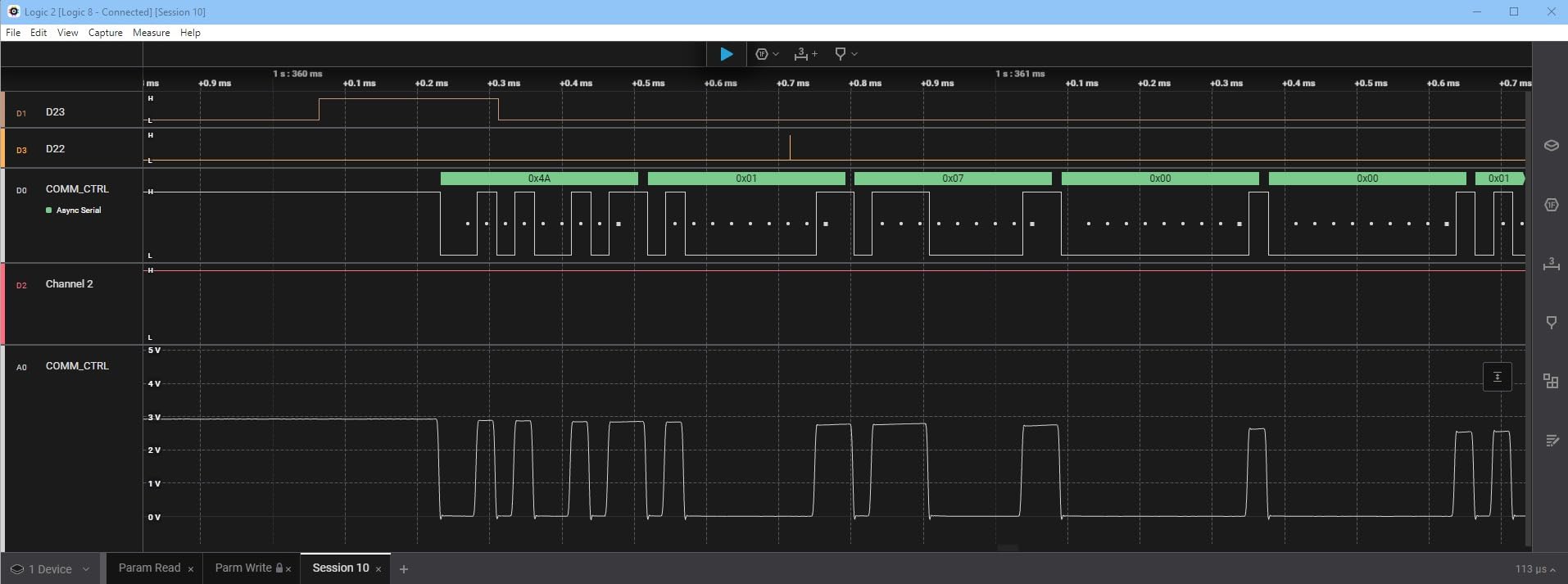
Capture depth is the quietly important specification. Rather than a fixed internal buffer, this device streams into host PC memory over USB 2.0, and the listed capacity is 10 billion plus digital samples and 500 million plus analog samples. For an Arduino maker that means you can record a long startup sequence, a full boot conversation, or minutes of bus traffic and then go back and find the millisecond that matters.
Two limits come up in the reviews. The USB 2.0 interface is the older standard, so raw throughput sits below what a USB 3.0 device can move, which matters more on fast signals than on slow ones. And analog sampling at 10 MS/s is modest, fine for watching a rail or a slow ramp but not a substitute for a real scope on anything with interesting shape.
Whether analog inputs earn their place on your bench
They earn it if your projects involve sensors with analog outputs, level shifters, comparators, or a power rail that behaves strangely. Being able to put a probe on a 3.3V supply and a probe on a clock line in the same capture is the feature that removes an entire class of guesswork, and it is the reason the dual-use design exists.
They do not earn it if everything you do is clean digital bus traffic. For that, the LA1010 gives you more channels for a fraction of the outlay, and this is worth saying plainly rather than recommending the expensive option by default.
Where the professional tier starts to cost you
At this level you are paying mostly for software, support and build quality, and that is a reasonable thing to pay for if the tool earns a living. If it sits in a drawer three weeks at a time, a clone plus free PulseView serves the same function. The 91-review count also tells you something useful: this is a device bought by people who already know what they need, so the crowd-sourced troubleshooting you would find for a cheap device simply does not exist here. You trade community knowledge for vendor support, and which side of that trade you prefer is a personal call.
6. LONELY BINARY 8-Channel Analyzer Kit – Best for Solder-Free Breadboard Work
LONELY BINARY Logic Analyzer Kit, 8 Channel 24MHz USB with Breakout Boards
24MHz 8-channel core
Breakout board with 2.54mm pins
Breadboard logic level adapter
USB-A and Type-C cables
Pros
- Breakout board and adapter make connections far easier than flying wire leads
- Ten test clips and five alligator clips in the box
- Solder-free setup for ESP32 Arduino and Raspberry Pi targets
- Traces and event triggering work well in open-source software
Cons
- 24MHz ceiling suits only low-speed digital work
- One-star reviews suggest some units arrive with poor accessories
- Three-star reviews cluster around documentation
- No bundled documentation or tutorial
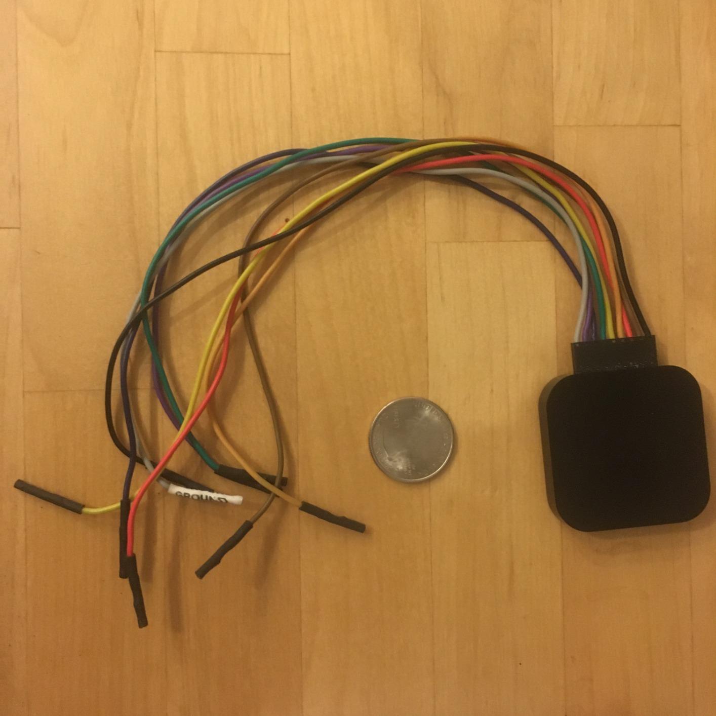
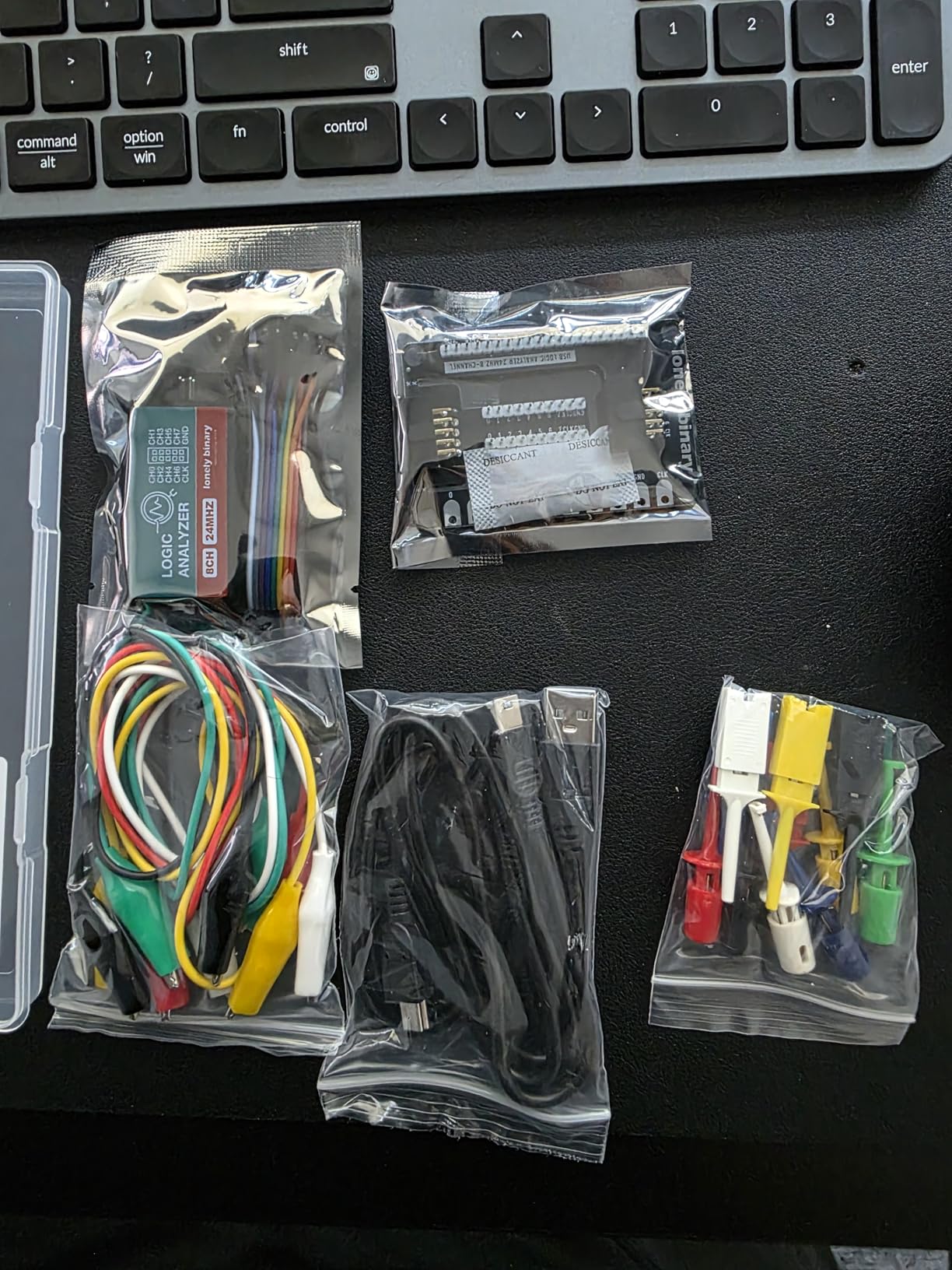
This kit exists because of a single insight: the hardest part of using a cheap logic analyzer is not the electronics, it is the connections. A bare clone gives you eight loose female-to-female jumpers, and getting those to sit on a breadboard while you also keep a serial monitor running is a genuinely fiddly process. This package solves it with a breakout board that exposes all eight channels to 2.54mm pins and pads, plus a dedicated logic level breadboard adapter for solder-free attachment to an ESP32, an Arduino or a Raspberry Pi.
The box also contains a logic level expansion board, both a USB-A and a USB Type-C cable, ten test clips, five alligator clips and a storage container. That sounds like a lot of small parts, and it is exactly the point: each of those items is a thing a bare clone leaves you to source separately.
Underneath, the analyzer core is the familiar 24MHz eight-channel design, which handles I2C, SPI and UART debugging without difficulty and runs on Windows, Mac, Linux and Ubuntu. Owners report clean traces and working event triggering in open-source software, and the 70 reviews average 4.2, with the accessory kit being the reason people are happy.
The criticism is concentrated and worth hearing. About 12% of ratings are one star, and those reviews consistently describe loose or poor-quality accessories, which suggests inconsistent batch quality rather than a design problem. Three-star reviews cluster on documentation and connection friction, and there is genuinely no tutorial in the box. For a kit aimed at people who have never done this before, missing instructions is a real gap.
Whether the adapter system changes your results
Yes, more than the specifications suggest. A poor connection produces edges that do not exist on the wire, and once you have seen phantom transitions you start doubting every capture. Rigid pins, a proper ground reference and clips that hold position remove an entire category of false readings, which is why so much of the beginner troubleshooting in this niche is really about mechanics rather than electronics.
The trade is that you are buying accessories as much as an analyzer. If you already own a good set of hooks and clips, the bare clone is a better use of the same money. If you do not, this kit removes the most common first-session failure.
When the 24MHz ceiling becomes the limit
It becomes the limit at roughly 4MHz SPI and above when you need to trust bit-level timing, on fast serial links, and on any bus where setup and hold times are the thing you are trying to measure. For I2C at 100KHz or 400KHz, UART, one-wire sensors, and any Arduino bus running at 8MHz SPI or below, the ceiling is theoretical. The accessories warranty runs a year, which is modest but at least documented.
7. Saleae Logic Pro 8 – Best for Fast Buses and Deep Capture
Logic Pro 8 (Black) – Saleae 8-Channel Logic Analyzer – Compatible with Windows, Mac, or Linux – Easy to Use, Ultra-Portable, Saves Time & Frustration
8 dual-use inputs
500 MS/s digital, 50 MS/s analog
USB 3.0 interface
10 billion plus digital samples
Pros
- 500 MS/s digital and 50 MS/s analog in one device
- Eight analog channels avoid a separate add-on
- Software is intuitive and fast to set up
- RS-232 interface on the professional model
Cons
- Sampling at the full 500 MS/s reportedly causes freezes needing a USB reconnect
- No true real-time streaming view
- Community extensions for advanced decoding are unmaintained
- Included USB cable is long and stiff
At 500 MS/s digital and 50 MS/s analog, this is the fastest device in the roundup and the highest rated at 4.8 out of 5, with roughly 90% of its 60 ratings at five stars. The USB 3.0 interface is the meaningful upgrade over the Logic 8, because throughput is what determines whether you can hold a high sample rate on several channels at once without dropping samples.
It also keeps the dual-use input design, with all eight inputs available as analog, which removes the need for a separate two-channel analog add-on. The RS-232 interface on the professional model is a small thing that saves a level shifter in exactly the situations where a beginner forgets to add one. Software quality is the recurring theme in the reviews: intuitive, quick to start, easy to learn, and improving regularly.
What 500 MS/s actually buys
Two nanosecond resolution. That is the point at which you can see ringing on an edge, measure propagation delay between a clock and a data line, and characterize a signal rather than merely detect it. It is the right tool for SPI running at 16MHz or faster, memory buses, and any measurement where setup and hold margins are the actual question.
It is also overkill for a sensor that talks I2C at 400KHz. At that speed, 24MHz already gives you around 60 samples per bit and nothing is missing. Buying this device for a project that does not need it is the fastest way to waste money in this category.
The two complaints you should know about
Owners report that sampling at the full 500 MS/s causes systematic freezes that require unplugging and reconnecting the USB cable, which is a real problem on a long capture. The other is the absence of a true real-time streaming view; if your workflow is watching a signal change as you turn a knob, this does not support it, and no logic analyzer in this roundup does. Also worth knowing: community extensions for advanced decoding have gone unmaintained and no longer compile, so do not plan a project around them.
8. DSLogic Plus 16-Channel 400MHz – Best Wide Capture on a Single Screen
DreamSourceLab DSLogic Plus USB-Based Logic Analyzer with 400MHz Sampling Rate, 256Mbits Memory, USB 2.0 Interface, 16 Channels
16 digital channels
400MHz buffered capture
256Mbits onboard SDRAM
DSView open-source software
Pros
- 400MHz buffered capture at 2.5 nanosecond resolution
- Adjustable threshold in 0.1V steps
- DSView is open source with nearly 100 protocol decoders
- Stream mode handles very long captures
- Coax signal lines plug straight into breadboards
Cons
- Digital only with no analog channels
- Triggering available only in buffered mode
- Documentation contains errors and is out of date
- Some third-party sellers ship a stripped accessory set
The DSLogic Plus solves a problem the Saleae units do not: how to get sixteen channels onto the screen at once, legibly, with a threshold you control. It captures 16 digital channels at up to 400MHz in buffer mode, which works out to 2.5 nanosecond resolution, and DSView is open-source software carrying nearly 100 protocol decoders, the largest library in this roundup by a wide margin.
Two capture modes make it flexible. Buffer mode writes to 256Mbits of onboard SDRAM, which is how you hold 400MHz across four channels, 200MHz across eight, or 100MHz across all sixteen. Stream mode transfers to host memory in real time for long sample durations, with rates of 100MHz on three channels, 50MHz on six, 25MHz on twelve and 20MHz on all sixteen, up to 16G samples of depth.
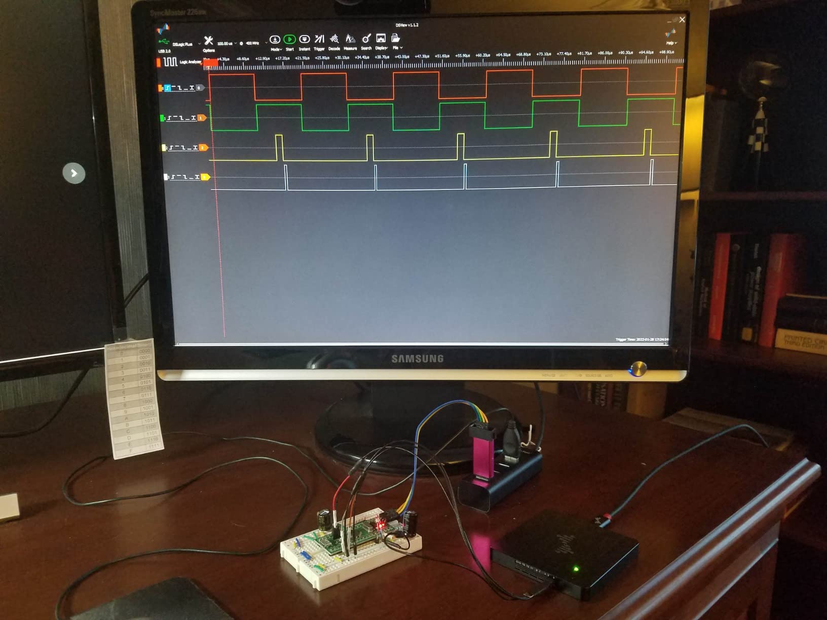
The adjustable threshold in 0.1V increments is the feature I would highlight above the raw bandwidth. A fixed threshold is the single most common cause of false edges on a slow or non-TTL signal, and being able to set it correctly for a 1.8V system or a 5V one removes an entire class of confusing captures. The coax signal lines with pins plug straight into a breadboard without grabbers, which solves the fiddliness problem better than most accessories in this roundup.
The 37 reviews average 4.6 and the feedback is strongly positive on decoding breadth, threshold control and trigger quality. What reviewers do flag: there are no analog channels at all, triggering only works in buffered mode, and the documentation contains errors and has not kept pace with the software.
Whether open-source software matters to you
It matters if you want to inspect how a decoder works, add your own, or avoid a subscription conversation entirely. DSView is inspectable and free, with a decoder library that covers industrial protocols the commercial tools charge for. It also means your capture files are not locked into a format only one vendor can read.
It matters less if you want a polished guided experience on day one, because the documentation gap is real and you will be searching for answers. The reported accessory shortfall also comes from third-party sellers shipping stripped bundles without the case or proper clips, so check what actually arrives.
9. EspoTek Labrador – Best Pocket All-in-One Teaching Tool
EspoTek Labrador: Easy-to-Use, Open-Source, All-in-One USB Oscilloscope, Signal Generator, Power Supply, Logic Analyzer, Multimeter for Windows, Mac, Linux, Android, Raspberry Pi
2-channel logic analyzer at 3MSPS
2-channel oscilloscope at 750ksps
2-channel waveform generator
Open source, 20g
Pros
- Pocket-sized at 20g and powered entirely over USB
- Open-source hardware and software with a Raspberry Pi install script
- Scope and waveform generator alongside the logic analyzer
- Great for teaching and for travel
Cons
- Only 2 channels at 3MSPS so a full 8-bit bus cannot be watched
- Reported channel-to-channel disagreement and drifting voltage readings
- Board pins do not align cleanly with breadboard spacing
- Android app is buggy and appears abandoned
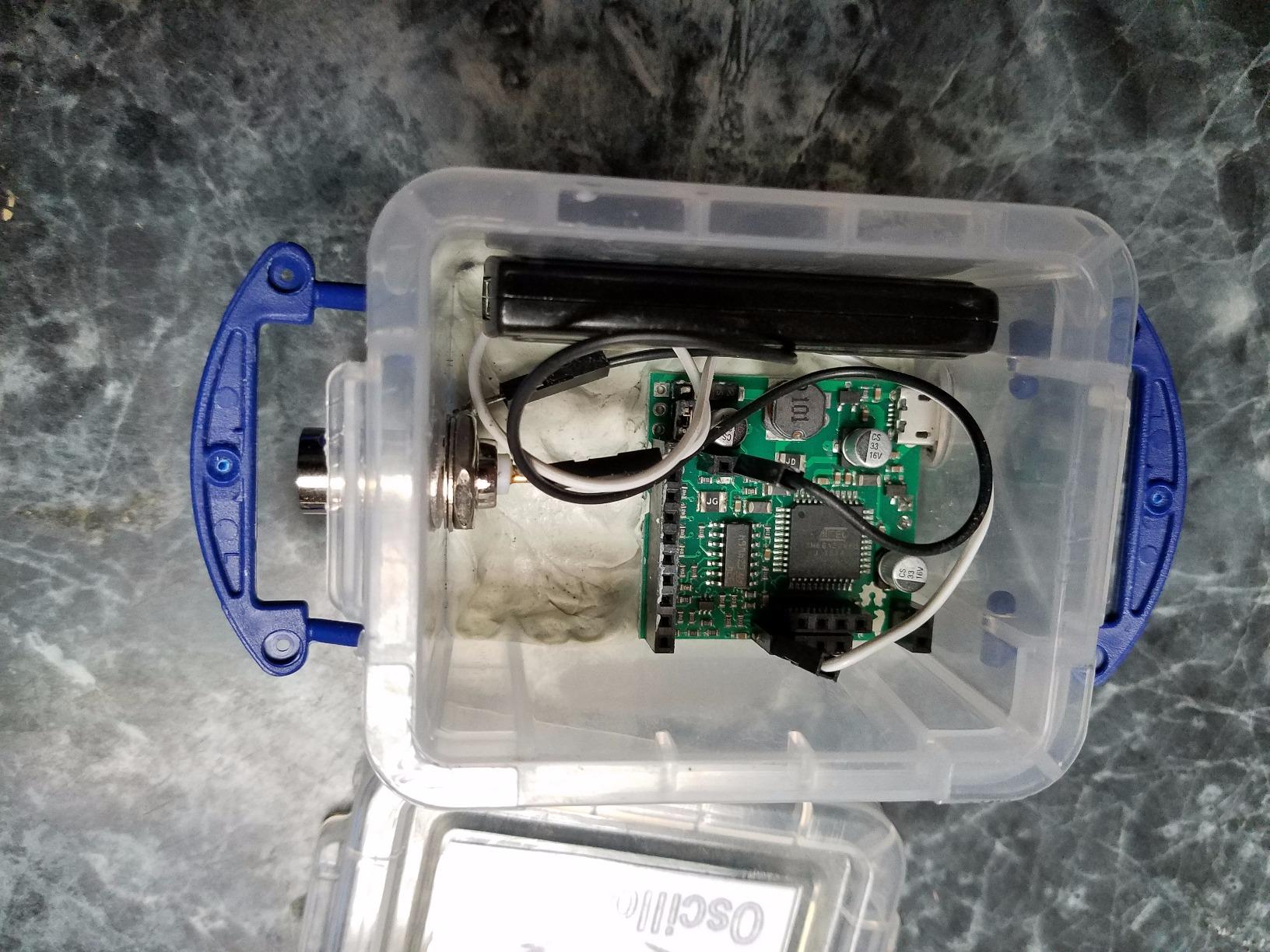
The Labrador is not really a logic analyzer with other features attached; it is a small lab. The analyzer channel is only two wide at 3MSPS per channel, but next to it sit a two-channel oscilloscope at 750ksps, a two-channel arbitrary waveform generator at 1MSPS, a 4.5V to 15V power supply with closed-loop feedback, and a multimeter for voltage, current, resistance and capacitance. All of it runs from USB and weighs 20 grams.
For a beginner, that combination is unusually complete. You can power a circuit, drive a known signal into it, watch the digital response on the analyzer channels, and check a voltage with the multimeter, all from one board and one set of software. The hardware and software are open source, with builds for Windows, macOS, Linux and a Raspberry Pi install script, which matters a great deal in a category where hobby software support is uneven.
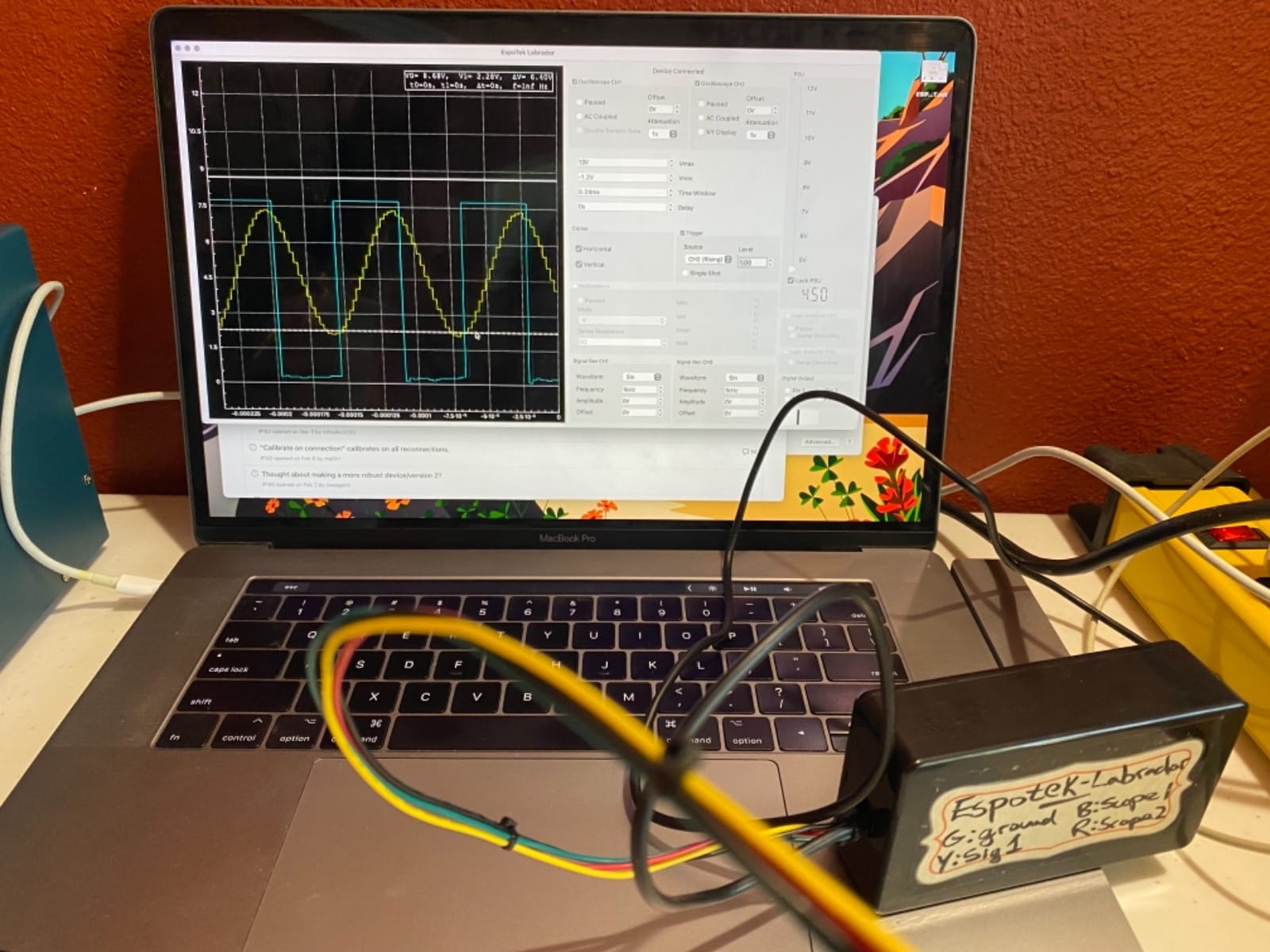
Two channels is the hard limit. You cannot watch a full 8-bit data bus, an SPI transaction with its four wires, or an I2C bus plus chip-select simultaneously. At 3MSPS it comfortably handles slow UART, I2C and I2S, so the limitation is channel count rather than speed for typical classroom and hobby traffic.
The 171 reviews average 4.2, and the feedback is consistent. Owners like the size, the open-source approach and the price; the criticisms are about accuracy and fit. There are reports of channel-to-channel measurement disagreement and voltage readings that drift away from a reference multimeter, the board pins do not align cleanly with standard breadboard spacing so the power pins may need bending, and the Android app is buggy and appears effectively abandoned. The tool is also not time-referenced, so traditional scope workflows are not available.
Whether a multi-tool beats a dedicated analyzer
For a learner, yes. The ability to generate a signal and then look at the response teaches bus timing far better than a passive capture, and having a power supply on the same board removes one of the most common beginner problems, which is probing an unpowered circuit. The multimeter covers the voltage checks that precede most debugging sessions.
For an active project, no. Two channels cannot follow a real bus, and the measurement accuracy complaints matter once you are chasing a millivolt-level fault. The software also does not save settings between sessions, which becomes irritating fast.
When this is the wrong tool entirely
Skip it if you are debugging SPI flash, anything with a multi-wire bus, or anything where an edge timing measurement decides the outcome. It is also the wrong choice if you need to trust a number, because a dedicated analyzer or a proper multimeter will give you readings you can rely on. This is a teaching and travel instrument, and treating it as a bench instrument is how people end up chasing drift that was never in their circuit.
10. KeeYees 24MHz 8-Channel with Test Hooks – Best for SMD Pin Probing
KeeYees USB Logic Analyzer Device with 12PCS 6 Colors Test Hook Clip Set USB Cable 24MHz 8CH 8 Channel UART IIC SPI Debug for Arduino FPGA M100 SCM
24MHz 8-channel analyzer
12 SMD test hook clips in 6 colors
sigrok decoding
Tutorial and libraries included
Pros
- Color-coded SMD test hooks solve the hardest part of probing small pins
- Works with sigrok for RS232 SPI I2C and 1-Wire
- Vendor supplies tutorial documentation demo code and libraries
- Very low cost for a working 8-channel 24MHz analyzer
Cons
- 24MHz sampling ceiling limits it to low-speed digital work
- Test hook clips can be finicky to attach to small pins
- Documentation quality is uneven
- Some colors share leads which makes signal identification harder
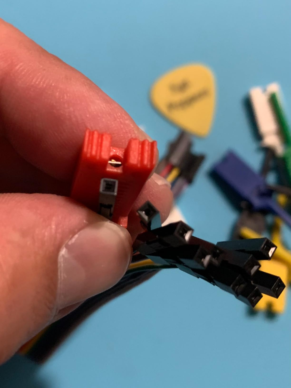
If your Arduino is talking to a surface-mount sensor or a memory chip soldered onto a breakout, the clips are what matter. This package bundles twelve SMD IC test hook clips in six colors, and that solves a problem that no other entry-level device in this roundup addresses: getting a reliable contact on a pin that is 0.5mm wide and surrounded by solder.
The analyzer core is the standard 24MHz eight-channel design, and it decodes UART, I2C, SPI, RS232 and one-wire through sigrok. Color-coding the leads means channel 0 is the same color in the clip bag, on the flywire, and on the waveform, which is exactly the kind of small quality-of-life detail that saves twenty minutes on a wide capture.
What stands out is the vendor support. A GitHub repository provides a tutorial, demo code, burning tools and class libraries, which is unusual at this tier and offsets the complaint that documentation quality is uneven. The 223 reviews average 4.4, and owners consistently name the color-coded hooks as the deciding factor rather than the specifications.
The honest criticisms are that the clips themselves are finicky to attach to very small pins, that documentation is inconsistent, and that some colors share leads, which makes identifying a signal harder rather than easier. The 24MHz ceiling and a 5V maximum input are the standard constraints of the class, and they matter on the same signals they matter everywhere else.
Whether SMD probing is part of your workflow
If you are working with anything smaller than a 0.1 inch header, the answer is yes, and this package saves you from buying a separate set of hooks and trying to keep them matched to channel numbers. It also works well on a bare chip, which is how you would read a flash part or tap a debug interface directly.
If your connections are all Dupont wires on a breadboard, the clips are dead weight and a plain analyzer with a better breakout would serve you better. Judge the bundle on whether you will actually touch surface-mount pins, not on the number of parts in the box.
When 24MHz is genuinely enough
Almost always, for the buses an Arduino Uno actually drives. I2C at 100KHz and 400KHz, UART at 9600 baud and above, one-wire sensors, and SPI at 4MHz or 8MHz all decode cleanly with room to spare. You will start to notice the ceiling only when capturing fast SPI flash, parallel buses, or anything where you need to see ringing on an edge. At that point, jump to a device with a higher sample rate and an adjustable threshold rather than pushing this one harder.
How to Choose a Logic Analyzer for Arduino Projects
Start with the bus, not the spec sheet. Almost every buying decision in this category can be made by answering four questions about the project you are actually working on, and only then comparing hardware.
How many wires do you need to watch at once? I2C is two, SPI is four, and anything with a chip-select or an interrupt line adds more. An eight-channel device covers almost everything a hobbyist does. Sixteen channels becomes necessary when you have a parallel data bus, a display, or a memory chip where you want the full byte on screen rather than one bit at a time. Two channels, as on the Labrador, is a teaching tool rather than a debugging tool.
How fast is the bus? This is where sample rate math matters, and we cover it in detail below. The short version is that 24MHz handles I2C, UART, one-wire and SPI up to about 8MHz with room to spare, and you need 100MHz or more only for fast SPI, memory buses and edge characterization.
Can you set the logic threshold? A fixed threshold between 1.0V and 1.8V is a compromise that suits 3.3V and 5V TTL and does poorly on 1.8V systems or on signals that rise slowly. An adjustable threshold in small increments removes an entire class of phantom-edge captures. Two devices in this roundup offer it, and it is worth paying for if you work with non-TTL levels.
What software will you use? This is the question most guides skip and it is the one that decides whether you enjoy the tool. The free sigrok and PulseView combination drives most of the budget devices here, and the community consensus across forum threads is that it has no meaningful bandwidth limitation and broader protocol coverage than many alternatives. Vendor software is generally smoother and better documented, and for one analyzer in the roundup it is the main reason to choose that device.
Budget is the fifth filter, and in this category it maps cleanly onto capability. The sub-twenty-dollar clones cover the buses an Arduino actually drives, the mid-tier devices add channel count, bandwidth and vendor software, and the professional units exist for analog inspection, deep capture and pattern generation. Paying for a professional analyzer to debug a 400KHz I2C sensor is the most common expensive mistake in this hobby, and it is entirely avoidable.
What Sample Rate Do You Actually Need for I2C, SPI and UART?
Sample rate is the specification hobbyists agonize over most and understand least. Here is the arithmetic, and it shows that for the buses an Arduino Uno drives, 24MHz is not a compromise but an excess.
I2C at 100KHz and 400KHz. A bit period at 100KHz is 10 microseconds. At 24MHz sampling you get 240 samples per bit, and at 400KHz you still get 60. A common fast-mode-plus bus at 1MHz drops that to 24 samples per bit, which remains more than enough to see setup time, hold time and every clock edge. No Arduino-level I2C traffic needs more than 24MHz, and even a 3.4MHz high-speed-mode bus stays within reach.
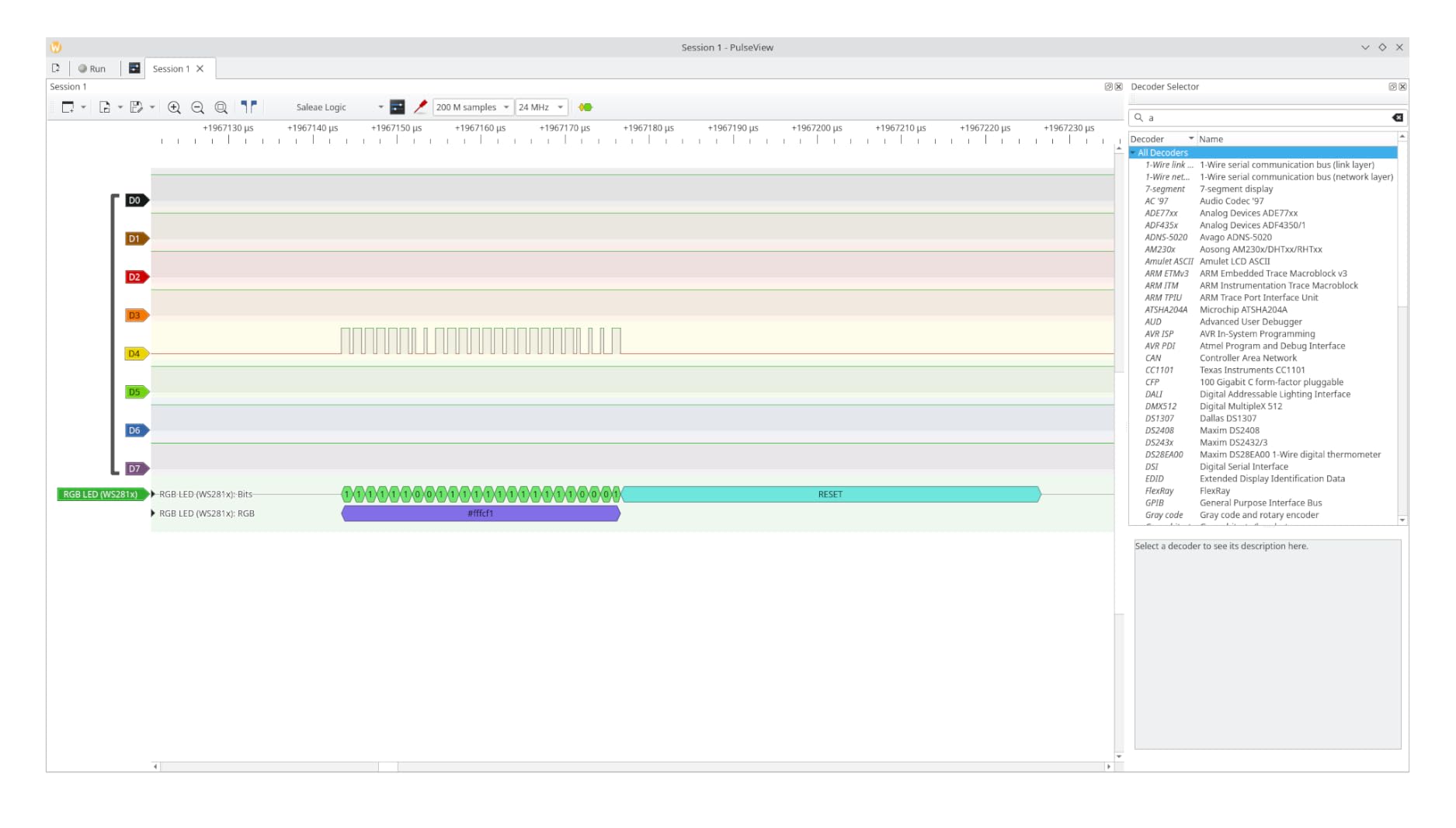
SPI at 4, 8 and 16MHz. This is where the arithmetic starts to matter. A 4MHz clock has a 250 nanosecond period, so 24MHz sampling gives about 6 samples per bit, which is fine for decoding but thin for measuring edge timing. At 8MHz you get 3 samples per bit, which decodes correctly and shows the shape of a transfer. At 16MHz you have 1.5 samples per bit, and that is genuinely marginal, because aliasing can invent edges that are not on the wire. If your project runs SPI at 16MHz or faster and you care about bit timing, step up to 100MHz or more.
UART. At 115200 baud, one bit takes about 8.7 microseconds, so a 24MHz analyzer samples roughly 208 times per bit. Even 921600 baud leaves 26 samples per bit. UART is the slowest bus on an Arduino and the easiest to capture, and the real difficulty there is usually picking the right polarity and baud rate in the decoder rather than having enough bandwidth.
One warning about interpreting any of this: sample rate is not the same as bandwidth. A 24MHz analyzer has a much lower analog bandwidth, and a signal that rises in under 40 nanoseconds will be smeared. If you are measuring rise time or analog behavior, you need a real oscilloscope.
Connecting a Logic Analyzer to an Arduino Without Garbage Captures
The most common reason a new owner decides their analyzer is faulty is a wiring mistake, not a hardware defect. Poor grounding produces captures that are unreadable, and until you understand why, it looks like the device is broken. This section is the fix, and it applies to every product in this roundup.
Connect the ground first. Every analyzer has a ground reference, and it must be tied to the ground of the circuit you are probing. On an Arduino Uno that is the GND pin on the header. Without this connection the analyzer has no reference for what zero volts means, and floating probe wires pick up noise that renders as garbage.
Use short connections. A logic analyzer is not a radio, but long flying leads on a breadboard act like antennas. Keep each probe under about 15 centimeters, route them away from the clock line if you can, and prefer clips or rigid pins over loose Dupont jumpers for anything fast.
Probe a stable ground, not a breadboard rail that might be split. Breadboard power rails break in the middle. If your analyzer reports everything as high or everything as low, check that your ground point is on the same rail segment as your circuit.
Start with the lowest sample rate that works. Dropping from 24MHz to 1MHz or 500KHz removes most false edges caused by breadboard noise and contact bounce. The 24MHz devices in this roundup all support selectable rates down to 25KHz for exactly this reason.
Check your threshold. On a 3.3V board, a fixed 1.8V threshold is too close to the noise floor for slow-rising signals. Adjustable-threshold devices handle this, and on fixed-threshold devices the lower sample rate is the workaround.
Verify the device on arrival. Before you depend on a capture, run a known-good signal through it: blink a pin at a known period, feed a square wave from a function generator, or loop an Arduino output back to an input. If a 1Hz square wave does not appear as a clean square wave in PulseView, the problem is the device or the connection, not your circuit.
Logic Analyzer vs Oscilloscope: Which One Do You Actually Need?
For Arduino debugging, you usually do not need an oscilloscope, and the forum consensus on this point has been consistent for years. A logic analyzer answers the questions an Arduino project actually asks: is this bus communicating, what address is it using, which byte is being sent, is the chip-select pulsing, and does the device acknowledge the transfer. It does that across eight or sixteen wires simultaneously, which is why it wins for any serial protocol.
An oscilloscope answers a different question: what does this signal actually look like. It shows you voltage amplitude in continuous time, and it is the right tool for rise time, ringing, overshoot, RC charge curves, power supply droop, motor noise and anything analog. A logic analyzer deliberately throws away that information. It only reports whether a wire was above or below its threshold at each sample instant.
The practical rule is simple. If you are asking which bytes went where, use a logic analyzer. If you are asking why a signal looks wrong, use an oscilloscope. If your project has both digital buses and analog behavior, the multi-use inputs on the two Saleae models and the all-in-one tools exist precisely because sometimes you need both in one capture.
One more comparison worth making. A logic analyzer tells you a transition happened but not its voltage, so a marginal or floating signal can look identical to a healthy one. If your problem is intermittent and disappears when you touch the circuit, suspect a signal integrity or grounding problem, and reach for the scope rather than the analyzer.
Using an Arduino or Raspberry Pi as a DIY Logic Analyzer
Yes, you can use an Arduino as a logic analyzer, and for some situations it is the sensible choice. The limitation is the sampling rate, so it works for slow signals and fails for anything fast.
The method is straightforward. Flash a sketch to the board that samples one or more pins in a tight loop, timestamps each change, and streams the results out over the serial port to your computer, where they are drawn as a waveform. A Raspberry Pi can do the same thing far faster, because its GPIO access and clock speed are much higher than an Arduino Uno’s, and the Pi version is the one people actually use for real protocols.
On an Arduino Uno running at 16MHz with digital reads, you can realistically get somewhere in the low thousands of samples per second with an eight-channel sketch, which is fine for slow UART and simple one-wire traffic and useless for I2C at 400KHz. A Raspberry Pi Pico or similar board closes most of that gap and can reach rates that make I2C and modest SPI practical. Boards with dedicated USB and better timing will beat a Uno comfortably.
When does the DIY route make sense? When you want to understand how a logic analyzer works, when you need a channel count you do not have, when the project is itself a learning exercise, or when you need to monitor a signal on a machine that cannot host a USB analyzer. When you want to decode I2C, SPI or UART and read the result as text, a device in this roundup will do it faster, more reliably and with a far better display for a fraction of the effort.
If you go the DIY route, treat the output as a teaching tool rather than a measurement instrument. It is a genuinely excellent way to understand why sample rate and ground reference matter, because you will hit both limits yourself within an hour.
Frequently Asked Questions
What is the best logic analyzer?
For most Arduino projects, the best logic analyzer is an 8-channel 24MHz unit that enumerates as a Saleae device, because free sigrok and PulseView drive it with no driver setup and 24MHz resolves every edge on I2C at 400KHz, UART, and SPI up to about 8MHz. Our top pick is the HiLetgo 24MHz 8-channel analyzer, with the innomaker LA1010 as the step-up when you need 16 channels and 100MHz, and the Comidox if you already own test leads.
Can I use an Arduino as a logic analyzer?
Yes, but with limits. You flash a sketch that samples the pins in a tight loop, timestamps each change, and streams results over serial to a waveform on your computer. An Arduino Uno realistically samples a few thousand times per second with multiple channels, which handles slow UART and simple one-wire traffic but not I2C at 400KHz or fast SPI. A Raspberry Pi samples much faster and is the better DIY board.
Can I use my Raspberry Pi as a logic analyzer?
Yes, and it is the stronger of the two DIY options. A Raspberry Pi or Pi Pico has far more GPIO bandwidth and clock headroom than an Arduino Uno, so it can sample fast enough to decode real I2C and moderate SPI traffic. It is still slower than a 24MHz USB analyzer, lacks an on-screen protocol decoder, and is best treated as a learning tool or a monitoring solution for a machine that cannot host USB hardware.
Why are logic analyzers so expensive?
The price gap buys bandwidth, channel count, analog inputs, on-board capture memory, build quality, support and software. An entry-level 24MHz 8-channel device streams every sample over USB with no buffer, while professional units capture hundreds of megahertz per second, store data in onboard memory, add analog channels, and ship polished vendor software with a large decoder library. For Arduino I2C, SPI and UART work, none of that is necessary, so the expensive tier is usually unnecessary.
What sample rate logic analyzer do I need?
For an Arduino, 24MHz is enough for almost everything. I2C at 100KHz and 400KHz uses 10 microseconds and 2.5 microseconds per bit, giving 240 and 60 samples per bit. SPI at 4MHz gives about 6 samples per bit and at 8MHz about 3, both decodable. SPI at 16MHz drops to 1.5 samples per bit, which is marginal, so step up to 100MHz or more for fast SPI, memory buses or edge timing work.
How do I connect a logic analyzer to an Arduino?
Connect the ground reference to the Arduino GND pin first, then attach probe wires to the signal lines you want to watch, plug the analyzer into your computer over USB, open PulseView, select the protocol decoder such as I2C or SPI, and assign each wire to a channel. Keep leads short, connect ground before probes, and start at a lower sample rate if the capture looks noisy. Most unreadable captures are grounding faults rather than hardware faults.
Does a logic analyzer work with PulseView?
Yes, and most entry-level devices in this roundup are built for it. The devices that enumerate as a Saleae Logic analyzer are recognized directly by sigrok and PulseView with no driver change, while Windows users of the bare clones may need to install the WinUSB driver with Zadig first. Devices with their own software such as the LA1010 with KingstVIS, the Digital Discovery with WaveForms and the DSLogic Plus with DSView can often also be used with PulseView, but their vendor tools are the intended experience.
Is a 24MHz logic analyzer enough for I2C?
Yes, comfortably. I2C at 100KHz gives a 10 microsecond bit period, which a 24MHz analyzer samples roughly 240 times. Even fast-mode-plus at 1MHz gives 24 samples per bit, and the clock, data, start, stop and acknowledge lines are all clearly visible with the annotation to prove it. Sample rate only becomes a constraint for high-speed serial links well above the I2C speeds an Arduino typically drives.
The Bottom Line on Logic Analyzers for Arduino Work
Start with an eight-channel 24MHz analyzer. That single recommendation covers the best logic analyzers for Arduino projects for almost everyone reading this, and the reason is arithmetic rather than opinion: I2C at 400KHz gives a 24MHz analyzer 60 samples per bit, SPI at 8MHz still gives 3, and UART gives hundreds. The hardware you are about to buy has more resolution than your Arduino’s buses can use.
Pick the HiLetgo for the smoothest first experience and the widest owner feedback base, the Comidox if you already have test leads, the KeeYees if you probe surface-mount pins, or the LONELY BINARY kit if you want a solder-free breadboard adapter and proper clips in the box. Step up to the innomaker LA1010 the day you need sixteen channels, a 100MHz ceiling or decoders for CAN and Modbus. Reach for the DSLogic Plus when you want a wide capture with an adjustable threshold and open-source software, and treat the Saleae Logic 8, the Logic Pro 8 and the Digilent Digital Discovery as tools for when a specific bandwidth, analog or pattern-generation need justifies them, not as defaults.
Whatever you choose, spend more attention on ground reference and sample rate than on the marketing. Nearly every unreadable capture in this category traces back to a missing ground or a rate set far above what the wiring can carry, and both are free to fix. And when you are ready to level up the rest of the bench, our guides to the best cordless drills for home projects and the best table saws for home projects cover the tools that pair well with a workbench built for this kind of work. If you cut your own enclosures and panels for the projects you are probing, the best wood for scroll saw projects roundup covers the stock choices that machine cleanly around a busy bench. This roundup was reviewed for 2026, and every device listed links to a live listing so you can check current availability and details for yourself.